PID Theory and Definitions
To support the safe and effective operation of the ALTAIR 5X PID, MSA believes operators should have a working knowledge of how the device functions, not just how to make it work. The information presented in this section supplements the hands-on operational instruction provided in the rest of the manual for the PID.
PID Theory
A photoionization detector (PID) uses an ultraviolet lamp to ionize the compound of interest. A current is produced in proportion to the concentration of the VOC present, and the concentration of the compound is shown on the device display.
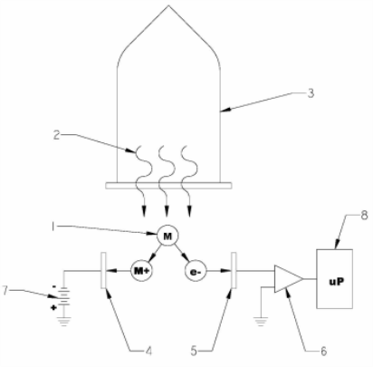
Figure 1 Typical photoionization sensor design
|
1 |
Molecules of Interest |
5 |
Electrodes |
|
2 |
High energy Vacuum Ultra Violet (VUV) radiation |
6 |
Amplifier |
|
3 |
UV lamp |
7 |
DC Source |
|
4 |
Electrodes |
8 |
Microprocessor |
Zero Gas
Zero gas is a reference gas used during calibration to zero the device. When a zero gas with no hydrocarbon content is introduced to the device, the detector will still respond with a small signal. This signal is a result of secondary background processes. During calibration, zero gas is applied to quantify the background ionization current. When only measuring concentration changes relative to a reference ambient environment, fresh air can be used as the zero gas. When background hydrocarbon vapors are present, MSA recommends using zero gas air.
Span Gas
Span gas is a reference gas used during calibration to determine the slope (response per unit concentration) of the calibrated response curve.
For the 0-2000 ppm PID sensor the only allowable calibration gas is 100 ppm isobutylene.
See Calibration for calibration instructions.
Response Factors
When a compound is ionized by photoionization, the ionized molecules are collected and converted to a current. This response is a characteristic property of the specific compound which is influenced by its molecular structure. The slope of the response curve (defined in picoamperes per ppm) is different for different chemicals. To properly report the concentration for a given sample gas, the ALTAIR 5X PID uses response factors. See PID Response Factor Table, for instructions on using the pre-programmed list of response factors.
WARNING!
It is very important to have an understanding of PID basics when changing PID settings. Failure to properly identify the VOC gas being measured and/or failures to select the correct Response Factor alarm values (exposure, STEL, TWA) that match the desired Response Factor and/or the correct lamp will result in erroneous readings or erroneous alarm limits that could cause death or serious personal injury.
The response factor is defined as the ratio of the detector response for isobutylene to the detector response for the sample gas. Response factors for a wide range of substances have been determined experimentally. These response factors are programmed into the device. Note that the calibrated response curve, and all programmed response factors are relative to isobutylene. Isobutylene has a response factor of one.
The response factor is a multiplier that compensates for the difference between the response of the sample gas and the response of isobutylene at 100ppm. Whenever the device detects the presence of a VOC, it uses the response factor for the user-assigned target gas to convert the signal to the correct, concentration. This is done by multiplying the equivalent isobutylene response by the response factor for the set sample gas. The isobutylene response curve is calculated at every calibration.
If the response factor is known, a device calibrated with isobutylene can be used to calculate the actual concentration of a target gas.
Calculating a Response Factor
To determine a response factor for a target chemical, perform the following simple procedure:
| 1. | Calibrate the ALTAIR 5X PID using isobutylene as the span gas. |
| 2. | On the device, set the sample gas name to isobutylene. |
| 3. | Apply a known concentration of the target chemical to the device and note the concentration reported in the display. |
The response factor for the target chemical relative to isobutylene:
|
RF target gas |
= |
Actual known concentration |
|
Concentration reported by device |
For example:
An operator is using a device that has been calibrated on isobutylene. The sample gas is set to isobutylene. While using this device to sample for hexane, the display reads 100 ppm. Since the response factor for hexane is 4.5, the actual concentration of hexane is:
Actual hexane concentration = 4.5 x 100 ppm = 450 ppm.
For example:
A device is calibrated on isobutylene, and has isobutylene defined as the sample gas. When sampling 106 ppm of benzene in air, the device reports a concentration of 200 ppm. In this example, the response factor for benzene relative to isobutylene would be:
|
RF benzene |
= |
106 ppm known concentration benzene |
=0.53 |
|
200 ppm reported |
When surveying, if benzene is selected as the sample gas in the Response Factor page, 0.53 will be used by the device as a response factor. The device will use this response factor to automatically correct the displayed concentration into PPM benzene.A target gas with a response factor between zero and one implies that the device has a higher detector response for that gas when compared to isobutylene. If the response factor is greater than one, the device has a lower detector response for this gas when compared to isobutylene.
WARNING!
It is very important to select the correct lamp setting during PID setup since PID response factors for a target chemical relative to isobutylene are different depending on what energy PID lamp is installed. See Device Setup for setup instructions.
Failure to follow this warning can result in inaccurate readings that could lead to serious injury or death.