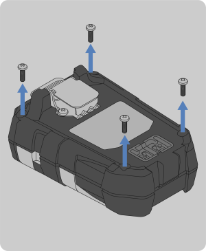
Back Housing Replacement

This section will briefly describe how to replace the back housing on the ALTAIR io 4 Gas Detection Wearable.
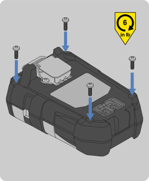
Tools Required:

Phillips head #1 torque screwdriver
Torx T6 torque screwdriver
1. Remove the four external screws with a Phillips head #1 torque screwdriver.
2. Remove the front housing and attached sensor gasket.

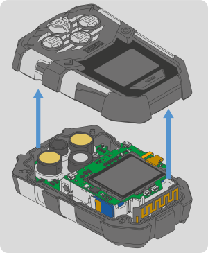
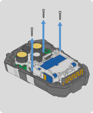
NOTE: The horn or sensors may stick to the gasket when the front housing is removed. If this occurs, see Step 4 of Horn Change to reinstall the horn or Step 4 of Sensor Change to reinstall the sensor.

3. Remove the display PCBA and display assembly by lifting it up.
4. Lift the display PCBA and display assembly away from the main board at the angle shown.
5. Remove the three internal screws with a Torx T6 torque screwdriver.
6. Lift the clear bracket and main board out of the back housing. Discard the back housing according to local regulations.
7. Install the main board into the replacement back housing.
8. Install the three replacement internal screws with a Torx T6 torque screwdriver. Torque to 2 in-lbs (0.23 N-m).
9. Take the display PCBA and display assembly, and insert the bottom left edge under the snap fit on the battery holder. Push the display PCBA down to engage the board to board connector.

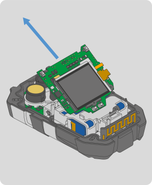
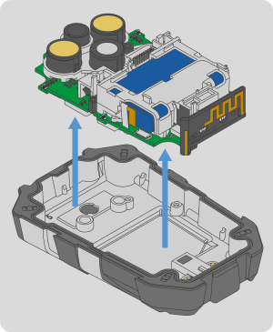
NOTE: Make sure the board to board connector is properly aligned.

10. Install the front housing.
11. Install the four replacement screws with a Phillips head #1 torque screwdriver. Torque to 6 in-lbs (0.68 N-m).
12. Calibrate the device per the instructions in the ALTAIR io 4 User Guide.