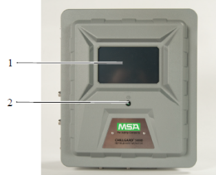
Identifying Your Unit
|
1 |
7″ resistive touchscreen user interface |
|
2 |
Power indicator |
NOTE: Optional strobe not shown.
|
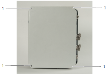
1 |
Mounting locations (10″ x 14 5/8″) |
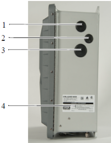
Figure 3 Right side of device
|
1 |
AC power wiring cutout |
|
2 |
Protective earth grounding cutout (optional) |
|
3 |
Relay wiring cutout |
|
4 |
Approval and unit identification label |
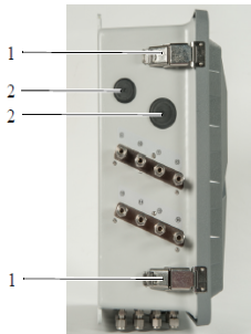
Figure 4 Left side of device
|
1 |
Latches (lockable with padlock) |
|
2 |
Signal wiring cutouts |
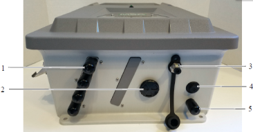
Figure 5 Bottom of device
|
1 |
Sample line identification labels |
|
2 |
Internal alarm sounder |
|
3 |
Calibration port |
|
4 |
IP rated vent |
|
5 |
Exhaust port (do not block) |
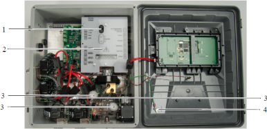
Figure 6 Internal touchpoints
|
1 |
Fuses |
|
2 |
AC wiring cover |
|
3 |
Internal filters |
|
4 |
ESD tie-off location |
WARNING!
Make sure the AC wiring cover is within the delivery and not damaged.
Failure to follow this warning can result in serious personal injury or death.