Using the DIP Switch
To change device settings through the DIP switch, do the following:
| 1. | Use a flat-blade screwdriver to remove the screws that attach the detector head to the base assembly. |
| 2. | Find the DIP switch. |
| 3. | Make the applicable switch assignments. |
| 4. | Cycle power to the device. |
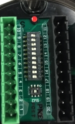
Figure 18 DIP Switch Location
On the DIP switch, the nomenclature "ON/CLOSED" is used when the switch is pushed in on the side labeled "ON" or "CLOSED" (opposite the side labeled "OPEN"). The nomenclature "OFF/OPEN" is used when the switch is pushed in on the side with the number related to the switch position or the side labeled "OPEN".
The time delay is the amount of time an Alarm Low condition continues before an Alarm High condition occurs.
|
|
Option |
|||||||||
|
Position |
1 |
2 |
3 |
4 |
5 |
6 |
7 |
8 |
9 |
10 |
|
High Sensitivity |
OFF |
OFF |
- |
- |
- |
- |
- |
- |
- |
- |
|
Medium Sensitivity |
ON |
OFF |
- |
- |
- |
- |
- |
- |
- |
- |
|
Low Sensitivity |
OFF |
ON |
- |
- |
- |
- |
- |
- |
- |
- |
|
2-second Alarm High Time Delay |
- |
- |
OFF |
ON |
- |
- |
- |
- |
- |
- |
|
4-second Alarm High Time Delay |
- |
- |
OFF |
OFF |
- |
- |
- |
- |
- |
- |
|
8-second Alarm High Time Delay |
- |
- |
ON |
OFF |
- |
- |
- |
- |
- |
- |
|
10-second Alarm High Time Delay |
- |
- |
ON |
ON |
- |
- |
- |
- |
- |
- |
|
Alarm High Non-Latching |
- |
- |
- |
- |
OFF |
- |
- |
- |
- |
- |
|
Alarm High Latching |
- |
- |
- |
- |
ON |
- |
- |
- |
- |
- |
|
Alarm Low Non-Latching |
- |
- |
- |
- |
- |
OFF |
- |
- |
- |
- |
|
Alarm Low Latching |
- |
- |
- |
- |
- |
ON |
- |
- |
- |
- |
|
Alarm High Normal Energized |
- |
- |
- |
- |
- |
- |
ON |
- |
- |
- |
|
Alarm High Normal De-Energized |
- |
- |
- |
- |
- |
- |
OFF |
- |
- |
- |
|
Alarm Low Normal Energized |
- |
- |
- |
- |
- |
- |
- |
ON |
- |
- |
|
Alarm Low Normal De-Energized |
- |
- |
- |
- |
- |
- |
- |
OFF |
- |
- |
|
Alternate LED |
- |
- |
- |
- |
- |
- |
- |
- |
- |
ON |
|
HART Enabled |
- |
- |
- |
- |
- |
- |
- |
- |
ON |
- |