Connection
|
|
|||
|
||||
|
||||
Restraint Lanyard
Connect one end to a suitable anchorage and the other end to the back D-Ring (or CSA Class A connector) of an approved full body harness or CSA Class P connector.
Energy-Absorbing Lanyard
Connect energy absorber to back D-ring of an approved full body harness (or CSA Class A connector) and other end to a suitable anchorage.
Twin Leg Energy-Absorbing Lanyard
Connect the middle snaphook of the twin lanyard to the back D-ring of an approved full body harness. Connect the snaphooks on the ends of the lanyard legs to suitable approved anchorages. Connect the snaphook at the end of one leg to an initial anchorage. Connect the snaphook at the end of the other leg to a secondary anchorage before moving and/or disconnecting from the initial anchorage.
See Connection Instructions for Pin Connector for instructions on pin connector installation.
Rebar Positioning Lanyards
Connect the two small snaphooks to the hip or waist attachment points on the harness with the large snaphook in front of your body. Attach the large snaphook to a suitable anchorage.
WARNING!
| • | When using a twin leg energy-absorbing lanyard, connect the center-mounted snaphook to the harness back D-Ring. Do not connect the snaphooks on the ends of the lanyard leg to your body support, as this can increase the possible free fall distance beyond allowable limits. Maintain tie-off while moving between anchorage locations. Do not disconnect from your initial position until you have first connected to another anchorage. When one leg is not in use, only attach to lanyard keeper on harness, not side or front D-ring. Do not allow lanyard legs to pass under arms, between legs or around neck. |
| • | When using rebar positioning lanyards, the user must be attached to an independent fall arrest system simultaneously. |
Failure to follow these warnings can result in serious personal injury or death.
Anchorage Connection
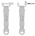
Tie-back Lanyard: connect the snaphook on the energy absorber to the back D-ring of the user’s full body harness. Be sure the snaphook’s gate is completely closed and locked. The user then connects the FP5K snaphook to the anchorage connector. Be sure the snaphook’s gate is completely closed and locked.
Tie-Back Connection
| 1. | Connect the snaphook on the energy absorber to the back D-ring of the user’s full body harness. Wrap the leg of the lanyard around a suitable anchorage. |
| 2. | Tie-back Lanyard: Connect the FP5K snaphook to the leg of the lanyard to create a closed loop. |
Floating D-ring: Connect the snaphook at the end of the leg to a floating D-Ring back on the leg of the lanyard to create a closed loop.
| 3. | Be sure the snaphook gate is completely closed, locked, and captures the leg of the lanyard. Inspect anchorage to assure the tie-back loop on the leg of the lanyard cannot be accidentally disengaged from the anchorage during use. |
Fall Arrest Attachment Element (D-ring) Extender
WARNING!
An attachment element extender is not to be attached directly to an anchorage or anchorage connector for fall arrest. An energy absorber must be used to limit maximum arrest forces to 1800 pounds (8 kN). The length of the attachment element extender may affect free fall distances and free fall clearance calculations.
Failure to follow this warning can result in serious personal injury or death.
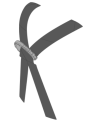
Pass hitchloop through back D-ring, then pull lanyard through hitchloop and pull taut. For fall arrest, always attach other elements of a personal fall arrest system to the free D-ring at the end of the extender. Do not attach two (or more) snaphooks or carabiners to the harness back D-ring (see Figure 3 Hitchloop Connection).
Leading Edge
The V-SERIES LEADING EDGE LANYARD has been tested for horizontal (Leading Edge) use over a steel edge without burrs using the methods in ANSI Z359.14-2014. Therefore the V-SERIES LEADING EDGE LANYARD may be used where a fall may occur over similar edges.
Leading Edge configurations shall only be used after all other hierarchy of controls, including restraint systems and overhead anchorages, have been exhausted.
Prior to use, leading edges must be evaluated by a qualified person (a person with a recognized degree or professional certificate and with extensive knowledge, training and experience in the fall protection and rescue field who is capable of designing, analyzing, evaluating and specifying fall protection and rescue systems). Avoid working where the lifeline will continuously or repeatedly abrade against sharp, hard, or abrasive edges. If the risk assessment indicated that an edge could damage the lifeline then eliminate such contact or protect edges using a pad or other means before the start of work.
Horizontal use or anchoring at the feet of the user should be limited wherever possible to avoid the potential for a swing fall and the possibility of the user striking a structure, potentially causing serious injury. To reduce the risk of a swing fall, it is preferable to anchor directly above the user.
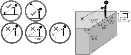
Anchor locations shall adhere to Figure 4 , including a redirection angle ≥ 90 degrees and set back ≥ 0 mm*** (0 ft ***); ensuring the correct function of the device in the event of a fall. Lateral movements to both sides of the center axis shall be limited to a maximum of 1.5 m (5 ft) as shown. The V-SERIES LANYARD anchorage point shall be at the user's foot level or above. Climbing above the anchorage point is not permitted (see Figure 4 ). Measures shall be taken to prevent use over unintended edges (such as on the opposite side of the anchorage or around corners).
If a fall over an edge is possible, special rescue measures shall be defined and trained. Consideration shall be given to assessing a suspended user without further loading or moving the lifeline over an edge.
A minimum fall clearance of 20 ft (6 m) is required for leading-edge use.
Figure 4 Acceptable Anchor Locations – Horizontal use with edge consideration
|
*** Ensure that setback distance meets requirements in anchorage connector manual and that the set-up does not allow lifeline connector to contact leading edge in the event of a fall. |
Connection Instructions for Pin Connector
WARNING!
|
The pin connector must only be used with the MSA Leading Edge Energy-absorbing Lanyard. Do not connect any other lifeline to the pin connector. Harnesses with split D-ring attachments are not suitable. For further information, or if doubt exists regarding the suitability of a specific harness type, contact MSA. |
|
|
|
Do not use a harness with split D-ring. |
Failure to follow this warning can result in serious personal injury or death.
The Leading Edge Lanyard attachment bracket allows connection to a full body harness just below the rear D-ring. The bracket shall only be used to connect the Leading Edge Lanyard to the harness. Any other devices shall be connected directly to the harness D-ring.
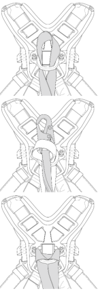
To Install the Leading Edge Lanyard to a Full Body Harness:
|
|
||||||
|
|
||||||
|
|
|
||||||
|
|
Following installation, and prior to use, the Leading Edge Lanyard shall be inspected by a second user.
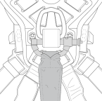
| • | Ensure the harness connector pin is passed behind both harness webbing straps between two slots in the dorsal D-shim. |
| • | Ensure the harness connector pin is fully housed through both bracket arms and locked in position; no red marking shall be visible on the pin. |
| • | Ensure the Leading Edge Lanyard is installed in the correct orientation, such that the Energy absorber hangs below the attachment bracket. |
| • | Ensure both harness straps are pulled tight and equally through the dorsal D-shim. |