Fall Clearance Charts
Ensure sufficient clearance exists to prevent striking an obstacle or structure during a fall. Insufficient clearance or obstructions can prevent the function of the V-TEC EDGE SRL.
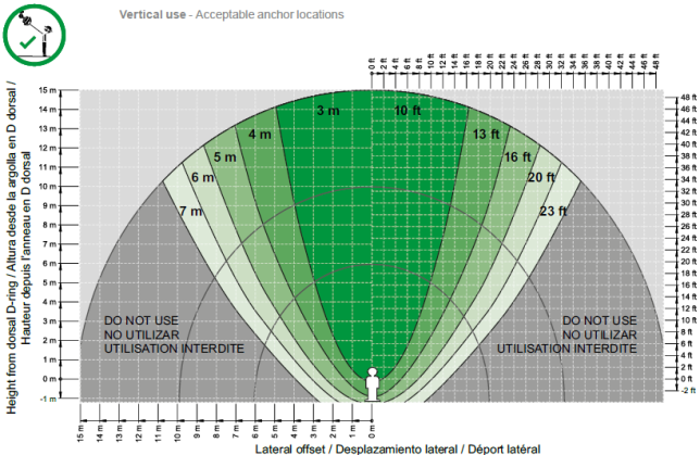
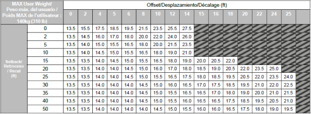
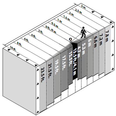
V-TEC EDGE SRL and absorber deployment is typically equal to a maximum of 1.4 m (55”) for a 140 kg (310 lbs) User. Consult (Vertical use) or (Horizontal use) for acceptable anchor locations in relation to the User and for minimum clearance requirements. Fall clearance is the vertical distance between the working platform and the first obstacle below (such as the next platform or ground). To accurately calculate sufficient fall clearance, the following is used: Fall clearance = Maximum Deployment + Lock-on (arrest) distance + Swing fall distance + Safety margin.
The clearance requirements in (Vertical Use) are based on free fall conditions. The presence of obstructions (such as structure edges) may reduce clearance requirements, but may introduce additional hazards, such as potential for laceration or impact injuries.
If the V-TEC EDGE SRL is attached to an anchor that may deflect or deploy in a fall, the deployment of that device shall be added to the minimum clearances specified in the below Acceptable Anchor Locations - Vertical Use Chart.
To reduce the potential for injury in a fall, work shall be carried out in such a way that the potential for a fall and the potential fall distance is minimized.
| Acceptable Anchor Locations - Vertical Use |
|---|
|
| V-TEC EDGE SRL LE Fall Clearance Chart |
|---|
|
| Acceptable Anchor Location - Horizontal (Leading Edge) Use |
|---|
|
Fall Clearance Charts
EN
Ensure sufficient clearance exists to prevent striking an obstacle or structure during a fall. Insufficient clearance or obstructions can prevent the function of the V-TEC EDGE SRL.
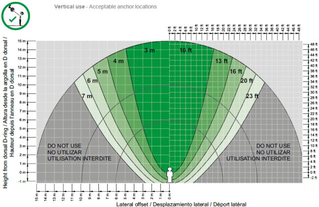
V-TEC EDGE SRL and absorber deployment is typically equal to a maximum of 1.4 m (55”) for a 140 kg (310 lbs) User. Consult (Vertical use) or (Horizontal use) for acceptable anchor locations in relation to the User and for minimum clearance requirements. Fall clearance is the vertical distance between the working platform and the first obstacle below (such as the next platform or ground). To accurately calculate sufficient fall clearance, the following is used: Fall clearance = Maximum Deployment + Lock-on (arrest) distance + Swing fall distance + Safety margin.
The clearance requirements in (Vertical Use) are based on free fall conditions. The presence of obstructions (such as structure edges) may reduce clearance requirements, but may introduce additional hazards, such as potential for laceration or impact injuries.
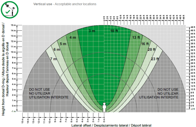
If the V-TEC EDGE SRL is attached to an anchor that may deflect or deploy in a fall, the deployment of that device shall be added to the minimum clearances specified in the below Acceptable Anchor Locations - Vertical Use Chart. The V-TEC EDGE SRL has not been tested for leading edge use with horizontal anchor lines (such as EN 795 Class C devices), dead-weight anchors (such as EN 795 Class E devices) or anchors which may deploy under load (e.g. standing seam roof posts). Therefore, only rigid anchors (such as EN 795 Class A, B or D devices) are suitable for leading edge use.
To reduce the potential for injury in a fall, work shall be carried out in such a way that the potential for a fall and the potential fall distance is minimized.
| Acceptable Anchor Locations - Vertical Use |
|---|
|
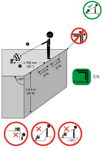
| Acceptable Anchor Location - Horizontal (Leading Edge) Use |
|---|
|
Fall Clearance Charts
GB (China)
Ensure sufficient clearance exists to prevent striking an obstacle or structure during a fall. Insufficient clearance or obstructions can prevent the function of the V-TEC EDGE SRL.
V-TEC EDGE SRL and absorber deployment is typically equal to a maximum of 1.4 m (55”) for a 140 kg (310 lbs) User. Consult (Vertical use) or (Horizontal use) for acceptable anchor locations in relation to the User and for minimum clearance requirements. Fall clearance is the vertical distance between the working platform and the first obstacle below (such as the next platform or ground). To accurately calculate sufficient fall clearance, the following is used: Fall clearance = Maximum Deployment + Lock-on (arrest) distance + Swing fall distance + Safety margin.
The clearance requirements in (Vertical Use) are based on free fall conditions. The presence of obstructions (such as structure edges) may reduce clearance requirements, but may introduce additional hazards, such as potential for laceration or impact injuries.
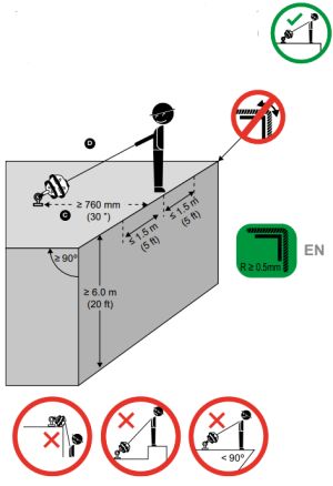
If the V-TEC EDGE SRL is attached to an anchor that may deflect or deploy in a fall, the deployment of that device shall be added to the minimum clearances specified inthe below Acceptable Anchor Locations - Vertical Use Chart. The V-TEC EDGE SRL has not been tested for leading edge use with horizontal anchor lines (such as EN 795 Class C devices), dead-weight anchors (such as EN 795 Class E devices) or anchors which may deploy under load (e.g. standing seam roof posts). Therefore, only rigid anchors (such as EN 795 Class A, B or D devices) are suitable for leading edge use.
To reduce the potential for injury in a fall, work shall be carried out in such a way that the potential for a fall and the potential fall distance is minimized.
| Acceptable Anchor Locations - Vertical Use |
|---|
|
| Acceptable Anchor Location - Horizontal (Leading Edge) Use |
|---|
|