Connecting Sensor to Transmitter Housing or Remote Junction Box
Sensors are not shipped attached to the main enclosure or junction box. All sensor modules interface with the transmitter via a digital four-terminal connection. Up to two sensors can be connected to a single transmitter, with each sensor getting a dedicated analog (4-20 mA) output.
Consider the sensor dimensions when choosing a mounting location for the transmitter or junction box.
To connect the sensor:
| 1. | Loosen the set screw located on the lid using a 1.5 mm Allen wrench. |
| 2. | Turn the transmitter or junction box lid counterclockwise to remove |
| 3. | Pull on the metal bail to remove the board stack and expose wiring connections. |
| 4. | Route the cable from the sensor through a conduit entry hole in the enclosure so that the sensor is oriented in the correct position (see Sensor Orientation for details). |
(Repeat to attach a second sensor to the ULTIMA X5000 transmitter).
| 5. | Connect the sensor to the "Sensor 1" position on the electronics assembly. |
| a. | If using a second sensor, connect it to the “Sensor 2” position. |
Notice
If only using one sensor, and it is connected to “Sensor 2” position, the ULTIMA X5000 will enter Sensor Missing fault. See Disable Sensor in Alarm Set Points for details on how to clear this fault.

Figure 11 Connecting Sensor to the Stack
NOTE: Sensor connectors come pre-wired on the sensor body.
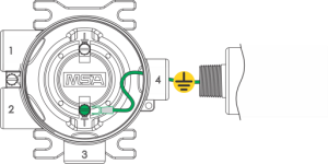
Figure 12 Grounding Sensor to Transmitter Housing
| 6. | Verify the sensor connector is firmly seated on the terminal board. |
| 7. | Attach the sensor's ground to either of the grounding screws inside the ULTIMA X5000 housing. |
| 8. | Replace the board stack legs into the four depressions in the housing. Push firmly on the board stack where indicated (see Figure 13 ). |

Figure 13 Highlighted areas show where to press when replacing a board stack.
Notice
| • | Avoid pressing on the left and right areas where the LEDs are located. Pressing directly on the display will damage the display and will void the warranty. |
| • | Ensure that the electronics assembly is fully engaged in the mounting holes. If not fully seated, the user interface buttons may not function properly. |
| 9. | Replace the cover by turning clockwise. |
| 10. | Tighten the set screw located on the lid using a 1.5 mm Allen wrench. |