Instructions for Power and Analog Output
WARNING!
Read all electrical warnings and wiring requirements before connecting power to the ULTIMA X5000.
Failure to follow this warning can result in serious personal injury or death.
The ULTIMA X5000 transmitter operates its analog output as a DC current source supporting a maximum load of 800 Ohms.
The red colored (4-pin) connector interfaces power and analog outputs 1 and 2. The HART interface is a separate, green colored (2-pin) connector.
The green colored (4-pin) connectors interface sensors one and two.
Using shielded cable is recommended. The cable shield should be terminated internal to the instrument enclosure using the crimp terminal provided (see Figure 30 ).
| 1. | Remove the ULTIMA X5000 cover by turning counter-clockwise. |
| 2. | Pull on the metal bail, removing electronics, to expose sensor and power connections. |
| 3. | Remove the red colored power connector. |
| 4. | Use a small, flat head screw driver to open wire entries on the connector. |
| 5. | Strip cable jacket to expose shield and the four individual wires. |
| 6. | Connect the power and analog output wires. Wire locations are marked on the cover plate (see Figure 30 Figure 29 ): |
|
|
a. |
+DC |
|
|
b. |
-DC |
|
|
c. |
mA1 - analog output of sensor 1 |
|
|
d. |
mA2 - analog output of sensor 2 |
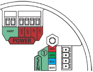
Figure 30 Power, HART, and Sensor Inputs
| 7. | Tighten screws on connector and tug gently on wires to ensure they are secure. |
| 8. | Connect shield of cable to base of instrument housing (see Figure 31 Figure 30 ). |

| 9. | Attach the connector to the board stack, making sure the appropriate wires are in the correct terminals. |
| 10. | Connect HART wires (for optional local HART port). |
| 11. | Connect an XCell or XIR PLUS sensor using the green connector. Sensor wires are already connected as shown on the cover plate (see Figure 32 Figure 31 ): |
|
|
a. |
+DC (RED) |
|
|
b. |
RS485 Com + (GRN) |
|
|
c. |
RS485 Com - (BLU) |
|
|
d. |
-DC (WHT) |

Figure 32 Connecting a Sensor to the Board
NOTE: Sensor connectors come pre-wired on the sensor body.
NOTE: Leaving exposed wire from the connector can electrically short the system.
| 12. | Replace the board stack by aligning the four metal standoffs with the four holes inside the ULTIMA X5000 housing. Push firmly on the board stack where indicated (see Figure 33 ). |

Figure 33 Highlighted areas show where to press when replacing a board stack
Notice
Ensure that the electronics assembly is fully engaged in the mounting holes. If not fully seated, the touch interface performance can be negatively affected
Notice
| • | Avoid pressing on the left and right areas where the LEDs are located. Pressing directly on the display will damage the display and will void the warranty. |
| • | Care must be taken to insure the X5000 inside glass surface is free of smudges/dirt and grease. Dirt and grease can interfere with the touch interface of the display. |
Table 7 ULTIMA X5000 Installation Outline Drawing
Model |
Document No. |
|
ULTIMA X5000 |
SK3015-1051 |