Relay and Power Connections
Relay Board Stack Overview
The ULTIMA X5000 can be purchased with three relays. Two of the relays can be configured for either de-energized (default) or energized and latching or non-latching (default). The third relay is a dedicated fault relay.
All electrical connections to internal relays can be made directly on the PC board. The board is labeled for Normally Open (NO) and Normally Closed (NC) de-energized state.
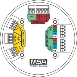
Figure 34 PC Board with Relays
|
|
|
|
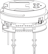
Figure 35 Non-Relay Board Stack |
Figure 36 Relay Board Stack |

Relay Specifications
Table 8 Relay Specifications
|
Relays |
SPDT (Single Pole Double Throw) |
|
|
|
Fault |
Normally Energized |
|
|
Warning |
Configurable |
|
|
Alarm |
Configurable |
|
Relay Rating |
|
|
|
|
125 or 250 VAC (Resistive) |
5A, 100K Cycles1.6 HP @ 250 VAC |
|
|
30 VDC (Resistive) |
5A |
If using AC power, the relay wires should not be run within the same conduit or cable tray as the DC power supplied to the ULTIMA X5000 or the ULTIMA X5000 junction box connection. A separate wire entry on the device should be used for AC power connected to the relays. The ULTIMA X5000 is built with an additional wire entry to allow this.
|
Exceeding the volt-amp rating of the relay can cause damage to the switching contacts. |
WARNING!
ULTIMA X5000 with relays is not approved for Division 2 or Zone 2 wiring methods. Use of Division 2 or Zone 2 wiring methods could lead to ignition of a hazardous atmosphere.
Failure to follow this warning can result in serious personal injury or death.
Relay Connections to Inductive Loads
If connecting the relays to motors, fluorescent lighting, or other inductive loads, it is necessary to suppress any sparks or inductive feedback that may occur at the relay contact. These effects may render the unit inoperative.
One way to reduce these effects is to install a Quencharc® (P/N 630413) across the load being switched.
Fault Relay Wiring and Configurations
The Fault Relay state in non-fault operating condition is Energized and terminal connections are supplied for Normally Closed and Normally Open.
The energized fault relay setting provides an electrical path for fail-safe relay operation. In the event of any failure, including loss of power, the relay will change to the de-energized state to indicate a fault condition.
The Fault Relay state cannot be reconfigured.
Relay Energy State and Terminal Connections
The ULTIMA X5000 relays can be selected as energized or de-energized on the device. The default configuration is the De- Energized state. The preferred relay energy state should be determined before making connections. Table 9 shows the terminal connections by energy state and is applicable to both relay 1 and relay 2.
Table 9 Relay Terminal Connections by Energy State
Energy State |
NC (Normally Closed) |
NO (Normally Open) |
|
De-Energized (default) |
Closed |
Open |
|
Energized |
Open |
Closed |