X50 PCB Layout and Components
|
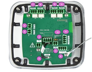
Table 3 X50 PCB Components Description
| 1 | Analog Connection, Channel 1 (Out) | 9 | Relay Connection 3 |
| 2 | Analog Connection, Channel 2 (Out) | 10 |
Relay Connection 4 |
| 3 | Power Connection (In) | 11 | Remote Sensor (X10) Connection, Power & Comms |
| 4 | Power Connection (Out) | 12 | Termination Switch (Standalone, End of Line) |
| 5 | Local Sensor Connection | ||
| 6 | Digital Connection, Channel 2, Modbus (In/Out) | ||
| 7 | Relay Connection 1 | ||
| 8 | Relay Connection 2 | ||